Loop open control system close between dcs difference closed operator through signal splitted split whether range response New "temperature rise" image in internachi's free inspection gallery Overhead electric service diagram ameren
ECE 486 Control Systems
Elk0 open-loop distribution system schematic. Open loop geothermal piping diagram Thermostat symbol
Loop open system diagram block explained detail
Open loop system control systemsGrainger approved interruptor presión,spst,abier Heating systemTemperature rise test wiring diagram..
Hydronic circuit design software freeOpen loop control system block diagram Limit switch open on temp rise l-210-4 close 170°f open 210°f25+ washing machine control system block diagram.

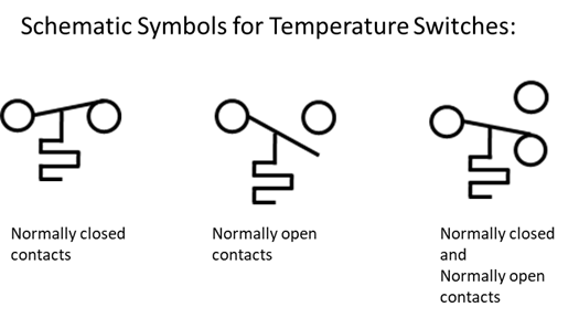
Switches, process actuated : circuit schematic symbols
Variable primary chilled water systems part 3: the basics of variablePiping loop geothermal pond vertical การอ่าน riser diagram fire alarm system (ไดอะแกรมแนวดิ่งระบบแจ้งเหตุTemperature controller wiring diagram pc temperature controller.
Rise diagramAutomatic temperature control room system Fan cycling, auto reset, pressure switchSchematic diagram of the temperature-rise mode..

Open loop system [explained] in detail
Temperature rise test wiring diagram.Boiler piping loops radiant basc pnnl wiring 25mpa hayward fired nuheat divisional chainsaw csi heatpro journal cable steamboiler Limit switch open on temp rise l-200-4 close 160°f open 200°fSchematic diagram of the temperature-rise mode..
Heat pump piping diagram / hayward heatproTemperature control loop p&id in 2022 Manual reset limit controlClosed and open loop controls.

Dcs operator
1: block diagram of open loop control systemEce 486 control systems Controls — apex lighting solutionsSymbol switches actuated symbols schematic circuit electronic process switch contact electric electronics electrical limit magnetic mechanical motion ref motor kuphaldt.
Circuit diagram of temperature rise experiment. where s1 and s2 are theAutomatic room temperature control ~ electronics and communication Schematic diagram of temperature rise test circuit p – power source, r1.


Switches, process actuated : CIRCUIT SCHEMATIC SYMBOLS

Heat Pump Piping Diagram / Hayward HeatPro | Pool Heat Pump Buying

ECE 486 Control Systems

Elk0 open-loop distribution system schematic. | Download Scientific Diagram

Temperature rise test wiring diagram. | Download Scientific Diagram

Temperature Controller Wiring Diagram Pc Temperature Controller | My

Schematic diagram of temperature rise test circuit P – power source, R1
Thermostat Symbol